
 0 Items £0.00

How do you wire a bilge pump? We show how to wire in a manual 12V bilge pump with a float switch, allowing the bilge pump to automatically activate when there is water in the boat bilge. Whether you have a Rule bilge pump, Whale bilge pump or another make, the wiring process is much the same. If you have an automatic bilge pump, then it already has a built-in float switch, but in this guide we focus on wiring a separate float switch with a manual electric bilge pump.
In the wiring installation of the 12V bilge pump the key elements are the 12V supply, a suitable fuse for protection, the float switch (which will be installed in the bilge), and a separate switch (installed inside the boat or cockpit) to turn on and off the electrics to the bilge pump system.
The full video guide can be seen here .....
The basis of the electric bilge pump installation and float switch wiring is that there are two switches connected in series, the first bilge pump switch is the one (usually inside the boat) that you use to turn on or off the electrics to the bilge pump, the second switch is the float switch which is installed in the boat bilge near the bilge pump, which will turn on the bilge pump when the water level rises, and then turn off again once the excess water has been pumped out of the bilge.
The bilge pumps and float switch featured in this video can be purchased from the following links
Bilge Pumps:
https://www.boatfittings.co.uk/c/marine_electrical_fitting/bilge_pumps
Bilge Pump Float Switch:
https://www.boatfittings.co.uk/p/bilge_pump_float_switch_20a_rating_mercury_free_
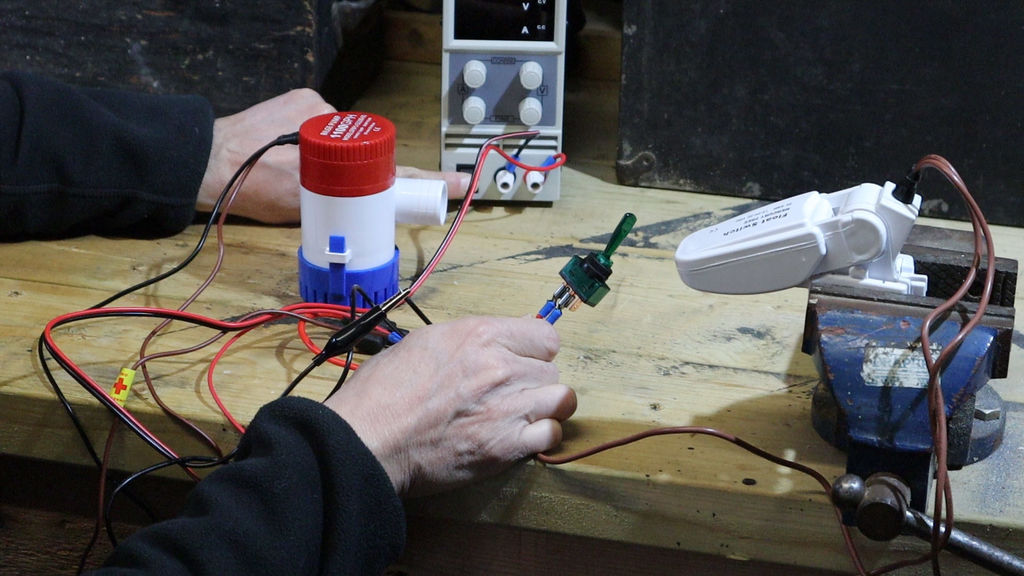
A simple electric bilge pump comes with two wires, a positive and a negative wire. The impeller of the bilge pump is designed to turn in a specific direction, therefore it is important that the positive and negative bilge pump wires are connected the correct way round to their power supply. Any bilge pump should be protected by a suitable fuse, typically in the range 5Amps to 15Amps, but check with the instructions for your particular pump. In this guide we show you how to wire a 1100 gallons per hour bilge pump with a bilge pump float switch.
Starting from the positive 12V feed, we have the protective fuse (in this case a 5Amp fuse), this is connected to the control switch. The output from the switch is then connected to one of the wires from the bilge float switch (it doesn’t matter which). The other wire from the bilge pump float switch is then connected to the positive wire from the 12V bilge pump itself, this completes the positive side of the circruit. For the negative side of the bilge pump wiring, the negative feed wire is connected to the negative wire of the bilge pump.
When connecting bilge pump wires, the connections should be kept in the dry. Where the wires enter the body of the bilge pump housing, the wires are sealed and the bilge pump itself can be fully submerged. Joints in the wiring, or connections to fuses and switches however should be kept safely above the bilge water level, or utilise waterproof connectors.
When choosing the position of the float switch, it should be approximately at the same height as the bilge pump, or a few cm higher. If the bilge pump float switch is too high then it will not be activated until the water has risen quite a long way. If the float switch is too low compared to the bilge pump then there would be a point where the float switch would have been activated but the water level would be below the bilge pump, hence the bilge pump would be pumping nothing but air.
When purchasing and wiring up bilge pumps ensure that the voltage of the bilge pumps match the boat supply voltage, most bilge pumps are 12V, but there are some 24V bilge pumps available.
If you found this guide useful or interesting you might like to sign up to our newsletter, so that we can let you know when our next guide has been published.
If so just click here .......